Space Electronics using COTS Components
For today's space missions the prospect of using so-called Commercial-off-the-shelf (COTS) components for the spacecraft's electronics is increasingly attractive, and indeed, even necessary for some missions. An example is the curiosity mars helicopter where one could speculate that the helicopter likely would have been too heavy to be airborne using space-grade hardware of equivalent processing power. The price of COTS components is also several orders of magnitude lower than their space-grade counterparts.
The glaring downside of COTS components is that they come with significant risk, as they are designed to operate at ground level, in an atmosphere. These risks can often be worth the advantages they bring. And the risk increase versus cost decrease can be included in the mission analysis.
One could argue that it is the use of COTS components that makes the so-called New-Space mission new.
Radiation Induced Failures
COTS components can fail in many exciting and non-intuitive ways when subjected to the space environment. These failure modes are typically not something an electronics engineer would encounter and indeed even consider when developing terrestrial electronics. In this article, I discuss some of the major issues in broad terms. There are many nuances and caveats that this text does not cover, but after reading this article, you are already miles ahead of anyone who is using straight-up terrestrial electronics circuit design.
Latch-Up
Latch-up is a phenomenon whereby High Energy Particles cause silicon to conduct in ways it is not designed to do. If we take a microcontroller as an example, the latch-up will cause the Supply lines of the chip to be shorted. The chip will behave like a radiation-triggered thyristor, and like the thyristor, the only way to leave the shorted state is to temporarily remove the supply voltage.
Latch-Up detection
A common practice in space electronics is to monitor the current to detect and act on latch-up events. If an overcurrent event occurs the supply line is set to zero volts, and then power is reapplied. The hope is that the circuit will no longer be in latch-up after this power cycle.
Be careful about where latch-up detection is placed. For instance, if the latch-up detection is only implemented on a EPS (Electrical Power System) it can be hard to determine if a high current event is due to a high-power consumer or a lower-power consumer with a latch-up.
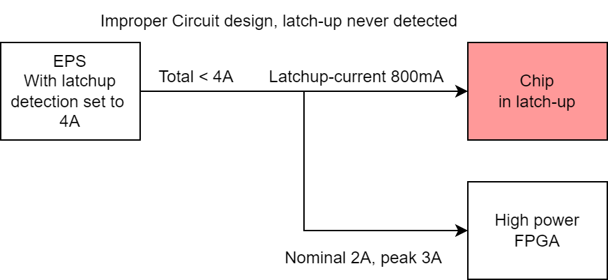
Another complicating factor is that many Linear and Switched power supplies have current limits, so it is important to set the latch-up protection lower than these limits, otherwise the fault may not be visible to the latch-up protection current sense.

Chip Isolation
It is a good idea to limit cascading failures in a circuit by adding current-limiting elements to the circuit. The easy solution is to add current-limiting resistors in between nodes of varying voltages. A practical example is a high-side current sense amplifier. While we would not expect the output to produce a voltage higher than the nominal operating range, we do not have insight into the exact configuration of the silicon. Hence it is good to assume, in an abundance of caution, that if a chip has more than one voltage supply, that all its pins can reach the highest voltage in the case of a failure. Doing so will help to identify which paths damaging current may take, and we are well-advised to place resistors on these paths.
A good approach is seeing what would happen if you rubbed steel wool around the pins of any given chip, and what would be the worst thing that can happen to the subsystem. Always do this mental exercise when adding an IC to your circuit.
Single Event Gate Rupture
Single Event Gate Rupture (SEGR) is a phenomenon that affects MOSFETs. It is triggered when a High energy particle strikes the Epilayer of the MOSFET. The exact failure mechanism is quite involved, but the end effect is that the MOSFET will conduct from the Gate along the ionisation path created by the particle. This can damage the gate or even destroy it, in what is dramatically called a Gate Rupture. The phenomenon happens when the MOSFET is in a high bias state with significant electric field gradients across it. In simpler terms, it happens when the MOSFET is "OFF" and does not conduct current but has a large voltage between the Source and the Drain.
Using MOSFETs in Space Electronics
MOSFETs are extremely common in terrestrial electronics and many electronics designers rely on them, however for space applications they should be treated with suspicion and proper derating is critical. Take the following precations when using MOSFETs
- N-Fets are most susceptible to SEGR
- Lower the voltage (De-rate) and ensure the MOSFET has a high voltage rating
- Try to keep the MOSFET on as much as possible to minimize the voltage across it!
- Use recent advancements in MOSFET technology such as GaN MOSFETs when possible (They are however more finicky to drive properly)
TID
The total ionising dose (TID) that a component has experienced during a mission can change its electrical parameters.
Flash memory can degrade and experience bit-flips. Flash memory is very common in COTS components such as microcontrollers and bulk storage memories. It is therefore important to be able to have some mitigation for failed or corrupted flash memory.
Shielding can have a significant effect on the TID experienced by a component. Naturally shielding is not something many smaller satellites can afford but the structure of the satellite does provide some shielding, so clever placement of sensitive components can be beneficial to consider.
Parameter drift
Electrical components can degrade and experience significant parameter drift due to radiation. In fact, many space-grade components specify their characteristic in a Pre-and-Post-Irradiation section. The important thing to understand is which way the parameters are going to drift and design in margin for being able to handle this drift. Fortunately, there are many papers and test reports available online, so it is often possible to find close matches to the component that you are investigating.
Mitigations
System Architecture
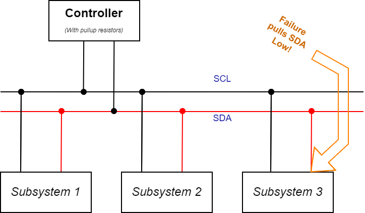
The way subsystems connect within the spacecraft is an important part of risk mitigation. For instance, in a spacecraft such as a CubeSat, a common way of connecting subsystems is with standard communication protocols, such as I2C, CAN, RS-485 or SPI. The issue lies in that the failure of one node can take out the entire bus.
In the case of I2C, a not unlikely failure mode is a node crashing during communication while holding the SDA or SCL line low, this will block any communication until a watchdog reboots the offending node. Therefore thinking about subsystem connections should include the prospect of any of the connected subsystems being responsible for making the bus inoperative. In the case of I2C, there are line drivers that are mounted before a target node that can detect a stuck line and let the common line go.
So when designing the communication scheme between components ensure to consider the following
- What happens if a node fails, can it block the bus?
- Can you add multiple independent communication buses?
- Is the bus already unstable on the ground? Radiation-induced degradation can make it worse
- What happens if a node has a catastrophic overvoltage event?
Watch Dogs
For terrestrial applications, a common way to guard against a software failure on an embedded microcontroller is using a watch-dog-timer module (WDT) in the MCU. However, relying only on the microcontroller-based WDT can be problematic as it too can be affected by radiation. It can be a good idea to include a hardware-based watchdog circuit that is kicked by continuously toggling a pin from software (and NOT using a hardware-based timer).
Degassing
When plastics and other volatile materials are exposed to the vacuum of the upper atmosphere and space, they may undergo a process known as de-gassing. This involves the evaporation of volatile substances in plastics and similar materials. These vapours can cause issues with condensation on optical instruments. Terrestrial COTS components are most often intended to be used in an atmosphere, and while most components will operate fine in a vacuum, their polymers may cause degassing issues. A common way to battle degassing is to bake the part, this is done by heating the part in a vacuum chamber for an extended period of time until the pressure stabilizes.