Introduction
Communication with embedded devices can be achieved in many ways. There are established ways, such as Wifi, Bluetooth, etc. However, any device that uses these interfaces usually is a hassle to set up. So in this project, I wanted to explore the simplest possible way to communicate to an embedded device: The screen of a smartphone.
The idea is quite simple:
- The device has a QR code which links to a website
- The website has the device configuration options
- The user configures the device and transmits the configuration by letting the website flash the screen of the smartphone
Flashing the screen
There are many ways to flash the screen of a phone, but they are not the same when it comes to flash repeatability. In my testing, I have found that the following means were not providing reliable flashes:
- HTML5 Canvas timed by setInterval
- Div set background timed by setInterval
So to get accurate timing, I found that the most reliable way was to generate a GIF which was then shown on the screen. To generate the GIF I created a hidden canvas and used the library gif.js. The library provides a nice interface to add an image that is shown for a certain duration, exactly what I needed.
Receiving the flashes
After solving the issue of generating a reliable flashing pattern on the phone, I focused on receiving the flashes on the embedded device.
Transimpedance Amplifier
The photodiode that reads the user's screen is amplified with a trans-impedance amplifier (TIA). The output of the TIA is fed to a comparator to generate a square wave output which is used to fire an ISR on the MCU.
Transimpedance Amplifier Explained
The transimpedance amplifier takes a current and amplifies it to a voltage. Its operation relies on the fact that an Opamp in negative feedback mode will keep the input voltages on its non-inverting and inverting input the same. Remember that (virtually) no current flows into the input of an opamp, so any current that the diode generates (Just like a solar panel, but smaller), will be carried all the way to the output of the opamp. As the current makes its way across the feedback resistor, a voltage drop is generated across the resistor in accordance with ohms law, U=RI. It is this voltage that the opamp has to produce to keep it's input at the same voltage, and this is how we arrive at a voltage output.

Screen Limitations
The major limitation in transmission speed is the screen used. For instance, with a normal computer screen, the light output looks like this graph:

The slow flanks are not a result of the transimpedance amplifier or the photodiode, they are the physical changes of light from the screen!
Another aspect of using phone screens is that they dim the screen using PWM, which will show up in the output of the TIA. To solve this I added fairly aggressive filtering to the TIA feedback resistor in the form of a 10 nF capacitor.
Choosing a modulation scheme
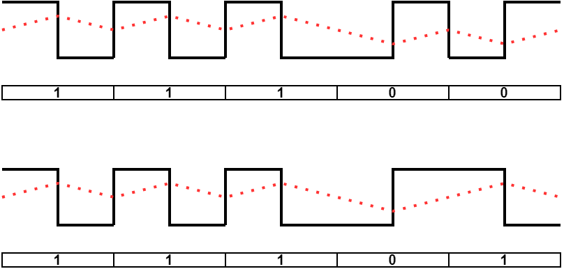
I choose to go with a simple Amplitude Shift Keying (ASK) modulation with a manchester encoded bitstream. Using manchester encoding is useful in ASK applications as there will always be a state-change, even for a train of equal data bits.
This fact comes in handy when we try to receive the signal, which will change both in amplitude and DC-Bias. We can simply create a running average of the received signal and compare the received samples to this average to determine if we are receiving a low or a high. The at-most two Lows or zero of the manchester encoding means we this running average will not get skewed even when a long sequence of '0's or '1's are sent.
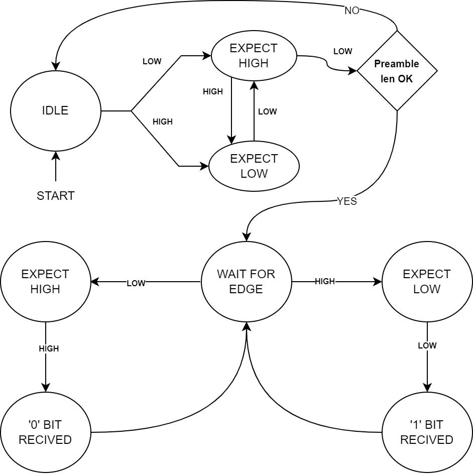
Receiving the signal
We can decode the ASK stream with the following state-machine
Real-world Demo
I used this communication scheme for a latch closer for a chicken door.